Product Introduce
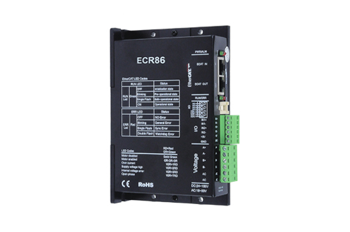
The ECR series is a high-performance bus controlled stepper motor driver which integrates the functions of intelligent motion controllers. The ECR series EtherCAT driver can be used as a standard EtherCAT slave operation, supporting CoE (CANopen over EtherCAT).
Naming rules
① Series name
EC: Refers to the EtherCAT bus type stepper drive series
② Control type
R: Open loop control
T: Closed-loop control
③ Adapted motor
42: Adapted to 42 stepper motors
57: Adapted to 57~60 stepper motors
86: Adapted to 86 stepper motors
④ Customized code
X2: Can drive two motors at the same time
Product features
● Supports CoE (CANopen over EtherCAT) and complies with CiA 402 standards
● Supports CSP, PP, PV, and Homing modes
● Minimum synchronization cycle 500us
● Dual port RJ45 connector for EtherCAT communication
● Control methods: open-loop control, closed-loop control/FOC control (supported by ECT series)
● Motor type: two-phase, three-phase
● Digital IO ports:
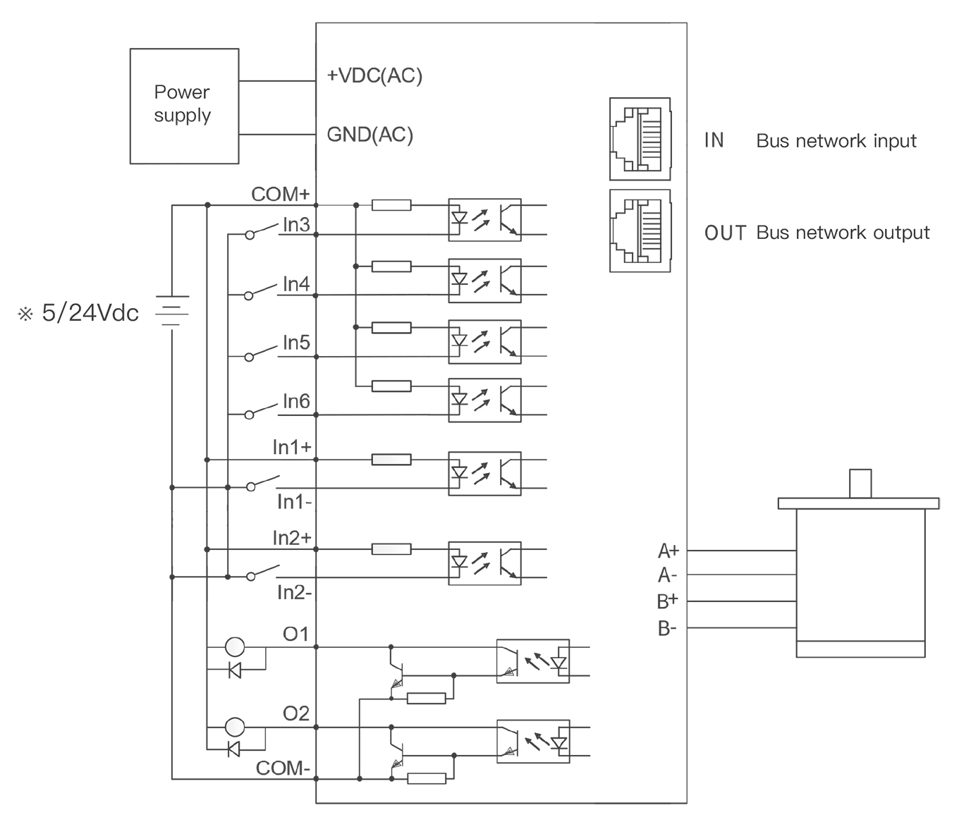
Six digital signal inputs with photoelectric isolation: IN1 and IN2 are 5V differential inputs, which can also be con-nected as 5V single ended inputs; IN3 to IN6 are 24V single ended inputs, with a common anode connection method;
Two digital signal outputs with photoelectric isolation: maximum withstand voltage 30V, maximum input or output current 100mA, common cathode connection method
ECR series driver models
|
ECR driver model |
Input power voltage |
Output peak current (A) |
Current (mA) |
Adapted motor |
|
Min |
Typical |
Max |
Min |
Max |
|
ECR57X2 |
24Vdc |
36Vdc |
80Vdc |
0.5 |
6 |
3000 |
below 60 frame |
|
ECR57 |
24Vdc |
36Vdc |
80Vdc |
0.5 |
6 |
3000 |
below 60 frame |
|
ECR86 |
24Vdc |
36Vdc |
80Vdc |
0.5 |
7 |
6000 |
below 86 frame |
Explanation:
1. Please use CAT5E (or higher level) Ethernet cable.
2. PNP input is not supported.
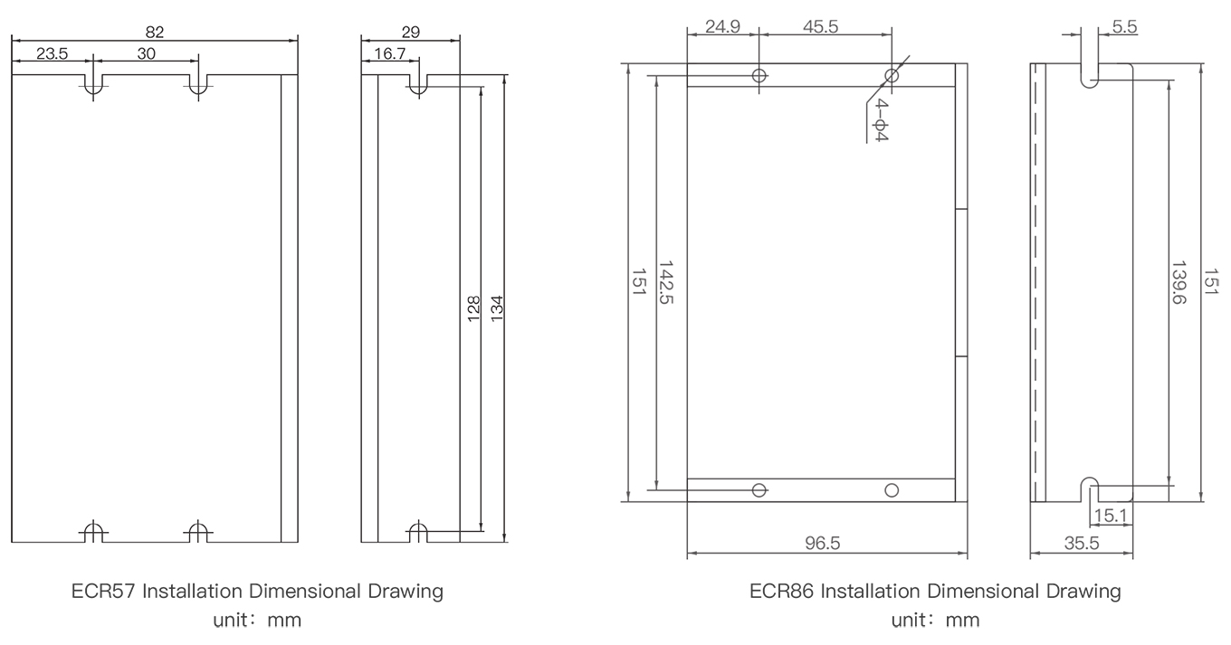
Dimensional Drawing
Wiring diagram
Attention: IN1+/IN1- and IN2+/IN2- are 5V input terminals. Do not directly connect input signals above this voltage, otherwise it will cause damage to the driver!
 VIDEO
VIDEO
 CONTACT